Gun Mounts, Elevation and Firing Controls - Churchill MkIII to MkVIII.
by C. Shillito
A topic that has often been subject to debate and speculation is the nature of the main armament elevation controls within the Churchill tanks particularly following the introduction of the Q.F. 6 pdr gun. This article seeks to illustrate, in chronological order, the varied mechanisms that were employed on the Churchill Mks and to provide some background as to why changes occurred.
When the 6-pdr mounting was first designed the decision was made to design a 'generic' mount which would be used in all 6-pdr armed tanks. This may seem a logical step but the 2-pdr mounts were pretty much unique to each tank that used them resulting in 10 differnet mounts!. Despite the fact that the mount itself was generic the other necessary 'attachment's' such as elevation control, depression stops and firing controls were subject to much variation and combination. A particular mount was therefore identified using both a Mk and No. designation:
"Mounting, 6-pdr & Besa Medium M.G. No.1, MkI"
The "Mk" designation generally refers to the mount (armour shield, cradle etc.) and the "No." designation indicates a particular combination of elevation, depression stop and firing controls.
For the 6-pdr there were two Mks of Mount. The MkI mount used a recuporator 'buffer' of a length that required a slot in the mantlet which was covered by a plate on the outer side. The mantlet consisted of a rolled armour plate onto which the trunion brackets and M.G. protector casting were then bolted. However, under test it was found that the M.G. protector when mounted in this way was prone to being 'shot off' and so a new mount, the MkII, was designed which incorporated the the mantlet, trunion brackets and M.G. protector into a single casting. For the MkII mount the buffers were aslso made shorter thereby removing the need for a 'slot' in the mantlet.
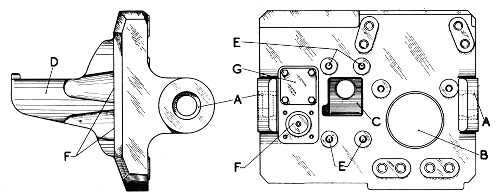
The mantlet incorporated two alternate mounting positions for the telescopic sight as illustrated by label F above. In Churchills only the lower position was used, the upper position being blanked off (G).
The mounting itself was designed to be capable of either "free elevation' (No.2) or geared (No.1) but it was originally decided that Churchills would have only geared elevation (and Crusader IIIs would have only free elevation). The early production MkIII Churchills would have been fitted with either "Mounting, 6-pdr & Besa Medium M.G. No.1 MkI" or "Mounting, 6-pdr & Besa Medium M.G. No.1 MkII"
Mounting, 6-pdr & Besa Medium M.G. No.1 MkI and II
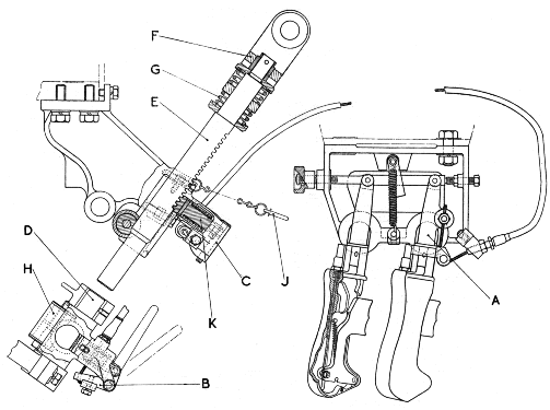
The illustration below shows that basic configuration of the elevation and firing controls..
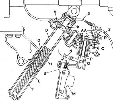
Elevation is achieved by rotating the hand crank (B). Not shown this diagram is the depression limiter mechanism which is achieved by a pair of rollers which traverse over cams set into the turret ring. This prevents bits of the tank from being accidentally shot off!. Incorporated in to the elevation crank handle is a firing trigger (M). The lever "R" selects which firing cable (S or T) the trigger will actuate and has three positions - Forward: 6-pdr, Backward: MG and Middle: Safe.
Nothing is ever simple with Churchills and the diagram above actually shows the MkII geared elevation. The first attempt, the MkI, apparently had straight cut rather than beveled gears but was found to be totally unsatisfactory in operation and although about 500 were produced they were quickly discarded and replaced by the Mark II geared type.
Mounting, 6-pdr & Besa Medium M.G. No.2 Mks.I and II
The problems with geared elevation seem to have continued despite the production of the MkII geared elevation system and to such a point that a decision was made at the end of May 1942 to abandon it all together and switch to the No.2 free elevation system as used in the Crusader III. So after only two months of Churchill MkIII production it would seem they were on their third change of elevation system (and as we shall see things don't improve much!)
This system operates by the gunner elevating the gun by physically lifting it using a sholder piece around his right shoulder. The gun could be 'locked' in elevation by pressing foreword on the trigger controls. The locking mechanism in this case is known as the Sprio Lock and is essentially a friction lock - the two counter winding spirals gripping the central shaft in such that once elevating has been locked any further movement results in the extension in length of the spiral thereby reducing its diameter thereby increasing the grip. In this way the shaft is gripped lightly at the elevation position but tighter should the gun be moved away from it. The official handbook for 6-pr mountings describes this action as providing "a positive but eleastic stop at any angle of elevation".
The firing controls have two separate triggers for the Besa and 6-pdr.
There is some evidence that the Spiro lock was used on some Churchills - When examining a Churchill MkIII/IV instruction book, there tucked into the inner sleeve was a brief document describing the spiro lock in detail and also mentioning that this applied not only to Mounting, 6-pdr & Besa M.G. No.2 MksI & II but also Mounting, 6-pdr & Besa M.G. No.2 Mk3 (as yet unmentioned!).
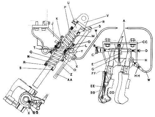
Unfortunately the Spiro lock proved to be most difficult to manufacture, one report even stating "the spring component of this lock is impossible to produce under normal production methods". There were also doubts as to its reliability under the "rough usage" of war conditions and so an alternative, the Rack Lock, was introduced.
As we can see the Rack Lock was a much simpler affair. When the firing control were pivoted foreword a toothed plunger was driven into a rack. The lock also included a screw clamp (H) such that if it was required to clamp the mounting in a position where the teeth did not engage the rack, the plunger could be withdrawn using the handle (B), the locking pin (J) inserted, and the clamp tightened. Despite its simplicity this design was not without problems and the gun metal sleeve was found to be liable to splitting and had to be replaced with one made from Manganese bronze. The ball bearings for the operating gear (which were the same as for the Spiro lock) were also modified several times due to difficulties of supply.
Mounting, 6-pdr & Besa Medium M.G. No.3 MkI
I know very little of this mount except that it must post date January 1943 (as no mention is made of it in The 6-Pdr Coaxial Mountings Handbook of that date) and that the spiro lock was at least one of the evelvation controls applied to it. Given that the rack-lock was supposed to supersede the spiro lock for the No.2 mount, it is odd that mention of the spiro lock is made for this apparently later mount. Perhaps there is a possibility that the spiro-lock made a 'comeback' and that it's production problems were eventually resolved.
It is odd that this designation should user "MkI" rather than the MkII which one might have expected. It is hard to believe that there would have been a return to bolted on trunions and M.G. protector.
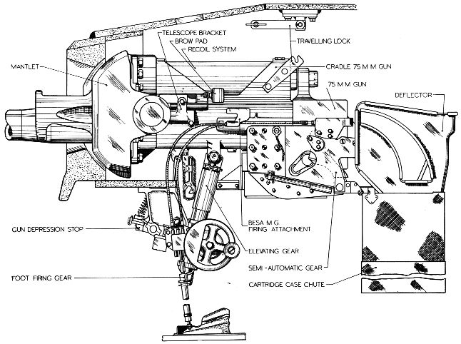
95mm Howitzer & Besa Medium. M.G. No.1, MkI
The Churchill MkV was armed with a 95mm Howitzer and with this type of weapon geared elevation is considered a necessity. This presented a real problem as the previous attempts at geared elevation in the Churchill had ended in 'failure'. Non the less, for the initial production vehicles at least, the only option was to fit a slightly modified version of the earlier MkII elevation gear.
The only noticeable change from that used on the early 6-pdr mount is that the firing selector lever has been replaced with a push-pull knob - Push = Besa MG, Pull = 95mm, Middle = Safe.
Mounting, 6pdr/75mm & Besa Medium M.G. No.1 MkI
With the 75mm armed Churchill MkVI a new mount designation was introduced "Mounting, 6pdr/75mm & Besa Medium M.G. No.2 MkI". This reflected the fact that the mount was dual purpose in that it could mount either the 6-pdr or 75mm gun. The original intention was for all MkVI and VII tanks to be produced with geared elevation using the Vickers MkIII geared elevation which had been designed as a replacement for the disastrous earlier MkI and MkII efforts. By late 1943 production was due to start on MkVI and VII but the Vickers MkIII elevation was not yet available (despite the fact that the failings of the previous geared elevation mechanisms had been pronounced a year and a half previously!). As a stop gap measure free elevation was used - but not employing the spiro or rack locks previously described but rather using a new system, the "vernier screw lock"
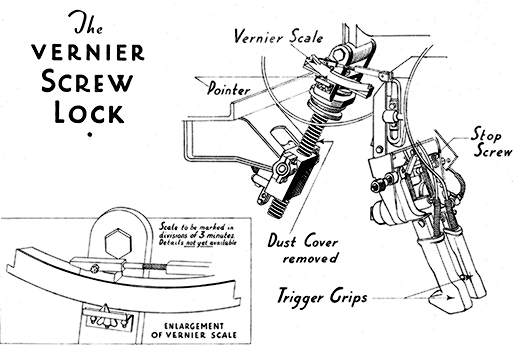
The vernier lock is very simple and works by the gunner manually setting the nominal locking position via turning the screw that engages the elevation shaft. There is some adjustment in the top end of the shaft and by moving the pistol grips a further 2 degrees of movement can be made.
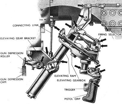
Eventually the Vickers MkIII elevating gear became available and entered production - it may also have been retrospectively fitted in the field. The Vickers MkIII elevating gear uses a geared handwheel and the the weapons are fired by depression of a foot pedal which is conneced via a rod linkage to the fire selector switch unit.
Mounting, 6pdr/75mm & Besa Medium M.G. No.2 MkI
This mount is virtually identical to the 6pdr/75mm & Besa Medium M.G. No.1 MkI mount except that where as on the No.1 mount the deflector bracket and semi-automatic gear were separate castings, on the No.2 mount has the left arm of the deflector bracket and the semi-automatic gear bracket fabricated as a single casting (the right arm being a separate casting).
Mounting, 6pdr/75mm & Besa Medium M.G. No.2 MkII
This mount was introduced with the Chruchill MkVII and is essentially the 6pdr/75mm & Besa Medium M.G. No.2 MkI mount but with a new mantlet.
Note how the manlet now sits inside a recess in the frontal turret armour. The manlet is a new casting with an exended front face to the M.G. protector and with only a single sight apperture.
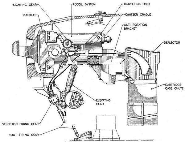
95mm Howitzer & Besa Medium. M.G. No.1, MkII
Once the Vickers MkIII elevating gear was available the 95mm mount was also reworked to remove the MkII gear. There are many reports as to the general inaccuracy of the Churchill MkV yet there is conflicting evidence from veterans who had no such experience. This may well be explained by the fact that the early MkVs were fitted with the MkII geared system and that by the time the vehicles saw active service this had been replaced by the superior Vickers MkIII system.
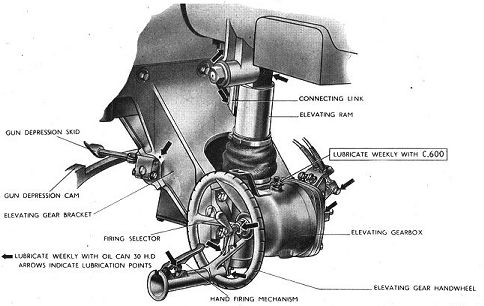
The 95mm Howitzer & Besa Medium. M.G. No.1, MkII mount differed from the MkI mount not only in the elevation mechanism but also in that the depression stop mechanism used skids rather than rollers. Initially the firing controls were incorporated into the elvating wheels as shown below.
 .
.
This was later modified to adopt a configuration similar to the 6pdr/75mm & Besa Medium M.G. No.2 MkI mount with firing control via foot pedal with rod linkage to selector switch.
95mm Howitzer & Besa Medium. M.G. No.2, MkI
The final mount to mention is that used in the Churchill MkVIII. This mount is similar to the "95mm Howitzer & Besa Medium. M.G. No.1, MkII" mount above but using a variation on the later style manlet and also with a foot pedal and firing selector box linked via a cable rather than a rod.
Mounting Table
|
MkIII
|
MkIV
|
MkV
|
MkVI
|
MkVII
|
MkVIII
|
|
| Mounting, 6-pdr & Besa Medium M.G. No.1 MkI |
*
|
?
|
|
|
|
|
| Mounting, 6-pdr & Besa Medium M.G. No.1 MkII |
*
|
*
|
|
|
|
|
| Mounting, 6-pdr & Besa Medium M.G. No.2 MkI |
?
|
|
|
|
|
|
| Mounting, 6-pdr & Besa Medium M.G. No.2 MkII |
|
*
|
|
|
|
|
| Mounting, 6-pdr & Besa Medium M.G. No.3 MkI |
|
?
|
|
|
|
|
| Mounting, 6pdr/75mm & Besa Medium M.G. No.1 MkI (free - vernier lock) |
|
|
|
*
|
|
|
| Mounting, 6pdr/75mm & Besa Medium M.G. No.1 MkI (Vickers geared) |
|
*
|
|
|||
| Mounting, 6pdr/75mm & Besa Medium M.G. No.2 MkI (free - vernier lock) |
|
*
|
|
|||
| Mounting, 6pdr/75mm & Besa Medium M.G. No.2 MkI (Vickers geared) |
|
|
|
*
|
|
|
| Mounting, 6pdr/75mm & Besa Medium M.G. No.2 MkII (free - vernier lock) |
|
*
|
||||
| Mounting, 6pdr/75mm & Besa Medium M.G. No.2 MkII (Vickers geared) |
|
*
|
||||
| Mounting, 95mm Howitzer & Besa Medium. M.G. No.1, MkI |
|
|
*
|
|
|
|
| Mounting, 95mm Howitzer & Besa Medium. M.G. No.1, MkII (firing trigger) |
*
|
|||||
| Mounting, 95mm Howitzer & Besa Medium. M.G. No.1, MkII (foot pedal) |
|
|
*
|
|
|
|
| Mounting, 95mm Howitzer & Besa Medium. M.G. No.2, MkI |
|
|
|
|
|
*
|
References & Sources:
6-pr and Besa Mounting - Report on Production. G.H. Gardner 27 Aug, 1942
Tank Board R.T.B. No. 43 (42) - C.G.R.D.'s Progress Report On Design Projects 20th May 1942
Tank Guns & Mountings - Book IIB - Handbook for 6-Pr. Co-axial Mountings (First Edition, January 1943).
Churchill VI & VII Armament (Provisional Draft of R.A.C. Military Training Paphlet No.35, Pt.39)
Service Instruction Book, Churchill III and IV (1st Edition July 1942)
Service Instruction Book, Churchill V & VI (First Edition April 1944)Service Instruction Book, Churchill VII & VIII (First Edition, June 1944).
Drivers Handbook for the Churchill Tank (Revised Edition, January1943)
.
© Chris Shillito 2014
Acknowledgement:
Special thanks to Steve Osfield for his long standing help and feedback
during the research of this article.