|
Suspension
One of the
most distinguishing features of the Churchill tank was the suspension
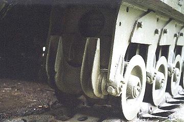
system. 44 small diameter wheels arranged on 22 separately sprung
bogies, 11 to each track. The overall appearance was quite unlike
any other British W.W.II tank and whilst at first glance all bogies
look appear identical there were a surprisingly number of subtle
differences between some of them.
Description
Each suspension
unit consisted of a bracket, frame, axle, wheels and springs.
On the earlier Mks all units were independent being separately
bolted to the pannier floor above. Each unit was bolted to the
next by a tie plate attached to the outer faces and secured with
lock nuts. The rear bolt on each plate was allowed a small end
clearance but the front bolt clamped the tie plate firmly. With
the introduction of the MkVII the suspension was strenghtened
by replacing the tie plate between units 2 and 3 was with a welded
plate producing a combined suspension unit.
This change
was also retrospectively applied to some earlier Mks, especially
those in service as AVREs, Bridglayers and ARVs which were required
to carry heavier loads. Whilst many such 'upgrade' modifications
occurred post war, it is interesting to note the AVRE at Greye
Sur Mer which was recovered from the beach in its original condition
also has the combined 2 & 3 bogie unit.
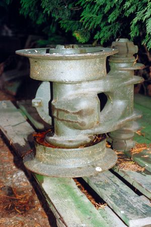
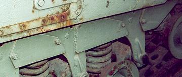
The bogie
support bracket was constructed from welded plates and incorporated
large boss on each side to which the fulcrum shaft was clamped.
A bogie frame, mounted on bronze bushes, pivots about the fulcrum
shaft which was hollow and acted as an oil reservoir, oil nipples
at each end. One end of the bogie frame carried the axle and the
other end formed the lug for the rebound stop. On the upper side
of the axle shaft boss was a hard steel knife edge against which
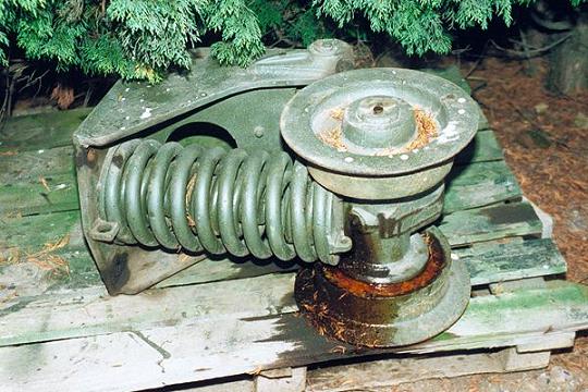
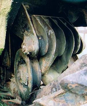
the lower spring seat pressed. Each bogie unit contained four
springs with the exception of number 11 which is unsprung. The
outer two springs carried the load, the next inner spring, the
"bumper" spring, controlled the last 3/4 inches of bump
through and the inner most spring was there simply to retain the
"bumper" spring in position. The knife edge itself was
used to minimise any buckling of the springs by giving them freedom
to assume their own axial alignment. Due to the working radius
of the wheel, some slight buckling of the springs was unavoidable
and so the springs were arranged to be straight in line when they
were at the point of maximum stress i.e. maximum bump.
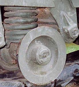
The wheels
themselves were 10" diameter and (perhaps surprisingly) were
simply push fitted on to the axle which rotated in white metal
bearings.
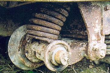
As with the
fulcrum shaft, the axle was hollow and acted as an oil reservoir,
being replenished via recessed nipples at the end of the axle.
There was another nipple at the centre of the bogie frame which
provided pressure relief.
Deflection
& Rebound
Bogies numbered
1, 2, 3, 9 and 10 also had varying degrees of curtailed rebound.
Bogie Number 1 only really came into use when either climbing
or 'nosing' . Bogie numbers 4 to 8 were allowed a full spring
deflection of 3 inches with a 2 inch rebound. Bogie number 11
was essentially a track tensioner rather than a strict suspension
unitand had a rebound of 2 inches and came into play every time
a gear change was made.
Fulcrum
Bosses
The bosses
into which the fulcrum shaft fitted were subject to some variation
amongst the Churchill series. On the early Churchills (MkI and
II) the bosses on all bogies were of the same pattern with the
fulcrum clamping nut below.
.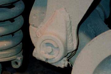
Later a strengthening
rib was added to the boss which also became longer....
...
and Bogies 1, 2, 9, 10 & 11 were modified to have shorter
bosses with the clamping nut moved to above the fulcrum shaft.
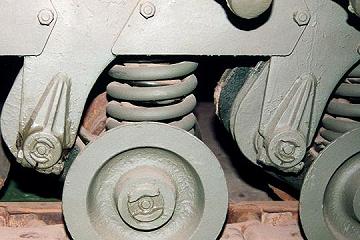
Bogie
Frame Rebound Lugs
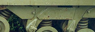
Most
bogie frame lugs were of a 'two pronged' as shown below..
However,
bogies 1 & 2 were different pattern bogie incorporating an
extra central strengthening rib.
. 
Bogie
11 was of yet another pattern being similar to 1 & 2 but without
the central rib.
Bogie
Frame Strengthening Strut
Bogies
1, 2, 9, 10 & 11 incorporate a strengthening strut which runs
across the bogie frame. On some vehicles bogie 8 also has the
additional strut (note this bogie has different pattern fulcrum
bosses than the others with similar struts). I've also come across
a strut on bogie 4 on one vehicle.
It
would appear that the orignal Churchill suspension units may not
have incorporated this strengthening strut as a report submitted
to the Tank Board by the Director of Armoured Fighting Vehicles
(A.C. Richardson) lists "Reinforced brackets Nos. 1, 2 and
11 bogies" as being and essential modification to ensure
battleworthyness of the Churchill in all theatres of war by spring
1942. The report recommennded that such reinforced brackets should
be included from tank No. 650.
Daily
Maintenance
As
one would expect, this suspension system required frequent maintenance.
The daily schedule (or every 50 miles if the daily mileage was
less than 50 miles) was to lubricate the bogie axles and fulcrum
shafts with gear oil (C.600) using a pressure gun and to inspect
and tighten the bolts on the on bogie bracket tie plates.
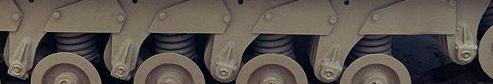
When
things get mixed!
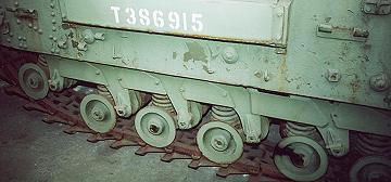
Despite
the variations in details the bogie units were by and large interchangeable
if the situation required. The photo below shows a ARV MkII which
has some of the bogies positions mixed. Tthe combined 2 &
3 bogie unit fitted at stations 8 and 7. possibly this was to
strenghten the suspension under the winch gear but more likely
it is an accident of 'restoration" or maintenance.
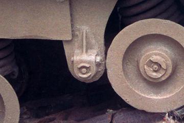
So
what would you expect to see at the number 2 & 3 stations
?
From
the fulcrum boss we can see that bogie number 2 is not correct.
Bogies 2 and 3 have been welded together via the tie plate which
is actually the one that should fit between 10 and 11. Whether
the welding was to create a combined bogie or whether it was necesary
just because this plate does not have a bolt hole in the necessary
place - who knows!
|