MkIV, V & VI Turret Variations.
By C. Shillito
This document seeks to identify some of the variations encountered with Churchill Tanks fitted with the Mk.IV cast turret. Diagrams have been prepared as the result of the study of many photographs and some suggestions for some of the differences/changes encountered are put forward for consideration and discussion. The diagrams shown below are not a definitive illustration of all the permutations and variations that existed, simply a record of what I have observed from the study of photographs. To help assist in the classification of the various turret configurations I have assigned a type designation - this is entirely of my own creation and does not represent, or imply the existence, any official designation.
The diagrams below use the following symbols:
|
|
These represents the ventilators used to remove fumes from the turret. |
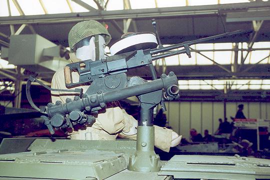
| Often found between the commander's cupola and loader's hatch is an attachment point for an anti-aircraft mount mounting twin Vickers light machine guns. This mount (PLM mount) had a shaft which passed through the turret allowing it to be traversed and fired from within. A similar mount was fitted to Humber Scout cars but it does not seem to have been popular with tank crews who rather than engage enemy aircraft, preferred to batten down the hatches - I've yet to see a photograph of such a mount actually attached to a Churchill. The attachment point for the PLM was not always present and all the configurations shown below are equally valid with, or without, it. | |
| This represents either the aerial of the WS19 A set and the aerial of the WS38 set (for Mk.VI & XLT). | |
| This represents either the aerial of the WS19 B set (troop). | |
| This is the standard periscope mounted on the loaders side of the turret. | |
| This represents a periscopic sight taken from a Sherman and used as part of the NA75 conversion. |
|
The layout shown in Figure 1 is that used on the first Mk.IV turrets and corresponds closely with that of the welded Mk.III turret (although with only one periscope). The ventilator is positioned to the front left near to the lifting attachment point (at the edge) and vane sight attachment point. At the rear of the turret are two aerials, the left hand being for the A Set the right the B Set. At the rear edge in the centre is a lifting attachment point. Adjacent to the periscope is the 2" bomb thrower aperture in front of which is another lifting attachment point. Photographic evidence would suggest that all Churchills with the shorter barrelled Mk.III 6-pdr had turrets of this configuration. Up-gunned Mk.VI 75mm and AVREs can also be found using this configuration. |
|||||
|
In Figure 2 we see a later variation on Figure 1. The ventilator is moved over to the right slightly and is now mounted inside a protective lip. Perhaps the ventilator was moved because in its original position it would cause fumes to be drawn across the gunner’s position.
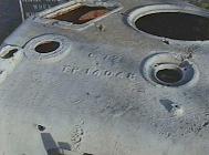
Figure 3. Shows a Mk.IV AVRE turret at the Combatton Combat Collection. On this example the PLM mounting point is not present. The photograph on the right shows the distinctive rear overhand that both type A and Type B turrets have. There is some evidence to show that this may have originally contained a series of air vents at the rear of the turret. Churchills armed with both Mk.III and Mk.V 6-pdrs are found using this layout as well as AVREs and up-gunned 75mm tanks |
|
|||||
|
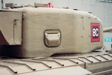
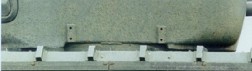
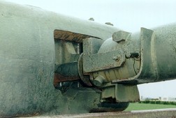
Figure 4. shows the final turret configuration found on MkIVs. This turret is also that upon which Churchill Mk.Vs and MkVIs we based. The ventilator has moved again and is now almost mounted centrally. Clearly with the ventilator in this position, the Mk.IV map shelf, usually underneath the turret roof above the main armament (see Mk.IV stowage diagrams) would have to have been removed or relocated. Aside from the obvious changes of ventilator position and mantlet aperture shape the turret was totally reshaped around the base to incorporate into the casting a protective ring around the the turret ring (shown in red opposite). On the right hand side of the turret there was insufficient width to continue and so an armour plate was bolted to the outside of the turret to over the turret ring in this area. Hanno's photo shows the mounting points for this plate and the protective ring is clearly visible below the right hand attachment point and extending right out to the front face of the turret. This casting subtly affects the appearance of both the front of the turret (see photo opposite) and the lower left hand side which now has a noticeable rounded bulge. The downward overhang at the rear of the earlier turrets has now been removed giving much more clearance at the back. Whilst all Mk V Turrets are of this configuration there is also photographic evidence showing this type of turret on MkIVs, AVREs and even NA75s. It may be that 'wider' use of this turret type was due to confusion of the numbers of close support tanks required which lead to an over production of turrets. However, I feel that the change was more significant and that the Type C was introduced as the production standard on the later production MkIV and MkVI tanks.
|
|||||
|
Figure 5. represents a configuration seen in only a few photographs (possibly of the same vehicle) but is also, intriguingly, shown in the stowage diagrams for the Mk.V (see Mr. Churchill's Tank). This would appear to represent a turret of the type B that has subsequently had its ventilator repositioned and a blanking plate placed over the original aperture. It may be that this configuration only applied to prototype Mk.Vs or perhaps came about during a shortage of available Mk.V turrets resulting in Mk.IV turrets being used instead (indeed the Mk.V stowage diagrams show a Mk.IV turret mantlet aperture). Note that whilst this diagram shows some similarity with those of the NA75 below, a modification from a NA75 to a Mk.V is highly improbable.
|
|
|||||
|
Mk
VI & Mk XLT
|
||||||
|
At the beginning of 1943 it was expected that the Churchill production run would come to an end sometime in the summer after 3500 vehicles had been produced. Vauxhall were then to manufacture a version of the Cromwell and built to their own drawings. Vauxhall estimated that the transition to Cromwell production would not be complete until early 1944 and so suggested that an order for a further 500 Churchills should be placed in order to keep their production facilities fully employed during the changeover period. The War office duly placed the order but specified that as many as possible of the new order should be equipped with the QF 75mm gun in a geared elevation mount. These tanks were designated Mk.VI but as a parallel exercise Mk.IIIs and Mk.IVs were also up-gunned to mount the 75mm but with free elevation. It would seem likely that there were relatively few (242 or so) Mk.VIs produced with considerably more Mk.IIIs and Mk.IVs being up-gunned. By May 1943 the Churchill had proved a success in Tunisia and as a direct result an order for a further 1000 was placed thereby ensuring that Vauxhalls would never switch to Cromwell production. Vauxhall's 'Cromwell' efforts did not go to waste however as it would seem likely that many elements of their proposed design and manufacture found there way instead into the Mk.VII Churchill not least the composite cast/welded turret. By the time the Mk.VIs came into production in late Autumn (November) 1943, the Mk.VII design was nearing completion and so many components and stowage arrangements were integrated into the Mk.VI. Whilst there are plenty of photographs of 75mm gunned Mk.IV tanks in North West Europe it is often difficult to ascertain whether these are Mk.IV (75mm) or Mk.VI. These vehicles are often covered in additional track links that make the identification of the turret components difficult. |
||||||
|
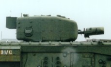
Figure 6. shows a typical Mk.VI turret. As the MkVI was effectively the last in the line of the MkIVs the turret is based upon a Type C (a 75mm armed tank with a type A or B turret will not be a MkVI but a MkIV 75!!). The cupola and loader's hatches have been replaced by the latter pattern as found on the initial builds of Mk.VII tanks. Note that the later All Round Vision (ARV) cupola is not fitted, but rather the twin periscope cupola with reinforcing 'strengthening struts mounted on the top of the hatches. The aerial configuration matches that of the Mk.VII which incorporated a WS No. 38 allowing communications with infantry units. The No.38 Set aerial is installed on the right, the main WS No.19 on the left and the WS No.19 Troop set aerial now mounted between them. |
|||||
|
Figure 7. represents a Mk.VI turret that has been fitted with the later ARV Cupola. There is some controversy over this configuration as some researchers attribute the fitting of the ARV cupola only to the Mk.XLT. In reality the ARV cupola was an easy upgrade that could quite easily have been made in the field. The appearance of an ARV cupola cannot alone be used to Identify any particular Mk. of Churchill. The specification of a Mk.XLT probably requires further explanation. In July 1944 Vauxhall put forward the following suggestions for future reworking of Churchills: "In about 4 - 5 months time Messrs. Vauxhall Motors will introduce into all re worked tanks:-
The result of this will be that in 4 - 5 months time all re worked Churchills will have immunity comparable with the present Heavy Churchill and the maximum speed of the vehicle will be reduced to give a performance comparable to the existing Heavy Churchill." Vauxhall's proposals were duly accepted and form the basis for the Mk.IX (reworked Mk.IV), Mk.X (reworked Mk.VI) and Mk.XI (reworked Mk.V) specifications. It would appear that the proposal to use Mk.VII turrets was rarely, if ever, applied and so rework vehicles retaining their original cast turrets carried the suffix LT (Light Turret). Given the original plan to use Mk.VII turrets it would therefore seem reasonable to assume that all LT variants would have been upgraded to Mk.VII configuration i.e. with ARV cupola. According to David Fletcher (Mr. Churchill's Tank), the frontal armour upgrade was to be achieved by fitting a Mk.VII type glacis, implying that a 'true Mk.XLT' would possess circular machine gun and driver's visor apertures. To date no photographs of a vehicle exhibiting all these characteristics has been discovered. There are however examples of 75mm armed Mk.IVs fitted with varying combinations of ARV cupola, strengthened suspension and appliqué armour. Whether to classify these as Mk.VIs, Mk.XLTs or experimental prototypes represents something of a dilemma. |
|
|||||
|
NA
75 Conversions
|
||||||
|
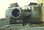
Figure 8. shows how the Mk.IV turret layout was initially adapted as part of the NA75 conversion. The Sherman armament used a periscopic sight for the gunner and the easiest conversion was therefore achieved by using a turret of type B turret as the ventilator aperture was aligned in just the right place for this sight. The ventilator was relocated replacing the right hand periscope. For those interested in learning more about the technicalities of the NA conversion see our N.A.75 Article. |
|
|||||
|
Figure 9. represents a well-documented NA75 conversion. Here we have a type C turret (as identified by the central ventilator and turret ring protector plate) with an aperture cut for the periscopic sight. As it would not seem reasonable to convert a Mk.V to a NA75 given their rarity (and late appearance in the Italy) the existence of this type of NA75 is proof that by early 1944 MkIVs were being produced with this type type of turret. Indeed this turret style appears to have been preferred for NA75s and this may be explained by a comment in the report on the initial trials of the prototype NA75 that criticised the ability of the ventilator to clear fumes from the turret. Having the ventilator mounted in the loaders periscope aperture as in fig. 7 would cause the fumes from the Besa to be drawn right across the turret to the loaders position. Having a central ventilator would certainly cure that problem
|
|||||
Summary of Turret Types Used
|
A
|
B
|
C
|
D
|
E
|
F
|
BNA
|
CNA
|
|
|
Mk.IV
6-pdr (Mk.III)
|
|
|
|
|
|
|
|
|
|
Mk.IV
6-pdr (Mk.V)
|
|
|
|
|
|
|
|
|
|
Mk.IV
(75mm)
|
|
|
|
|
|
|
|
|
|
Mk.IV
AVRE
|
|
|
|
|
|
|
|
|
|
Mk.IV
NA75
|
|
|
|
|
|
|
|
|
|
Mk.V
|
|
|
|
|
|
|
|
|
|
Mk.VI
|
|
|
|
|
|
|
|
|
|
Mk.XLT
|
Thanks
to Steve Osfield for help and advice offered during the preparation of
this article.
© Chris Shillito 2002, 2004