Engine & Transmission
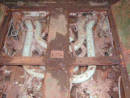 |
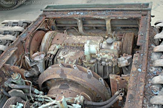
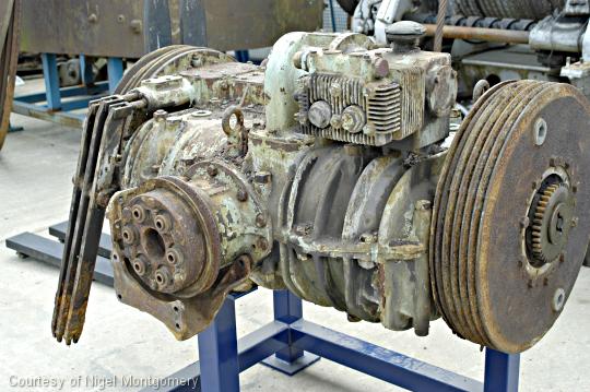
Engine prior to removal.
|
 |
|
 |
The Churchill engine was a 12-cylinder, 4 stroke, water-cooled, horizontally opposed petrol engine. It developed a nominal 350 B.H.P. at 2,200 r.p.m. |
 |
The long vertical cylinder to the left of the engine block is the oil filter and de-aerator. |
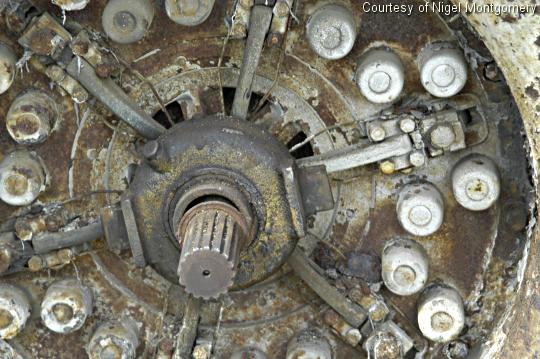 |
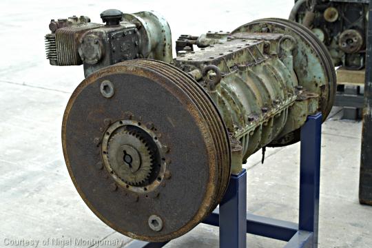
Close up of the clutch which is bolted to the fly wheel which forms one friction plate of the clutch. Clearly visible on the front face are the 24 retainers for the helical springs used to apply the pressure to the driven plate. Also, on the front face of the clutch can be seen the toggle levers (radiating from the centre) which relieve the spring pressure from the driven plate when disengaging the clutch. |
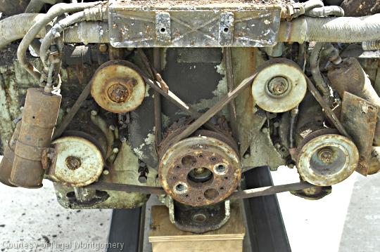 |
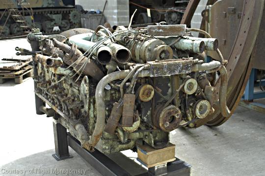
Front view of the engine. To the top behind the 'box' is the front pulley wheel of the main generator (you can see a belt from this running vertically down to the main drive pulley below - generator can be seen clearly in a photo above ). The pulley wheels
to the left and right are connected to water pumps. The upper pulley
wheels are tensioners. |
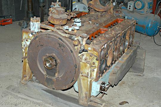 |
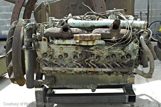
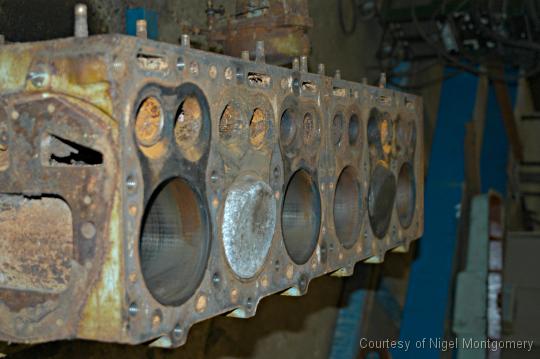
The stripped engine block. The clutch has been removed revealing the fly wheel. The cylinders are arranged in two blocks each of which is a single casting. The left hand block has the cylinders slight forward of those in the right hand block. |
 |
|
 |
|
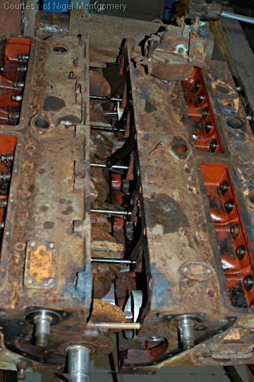 |
Here we're looking down on the engines as the left and right hand cylinder blocks are separated. |
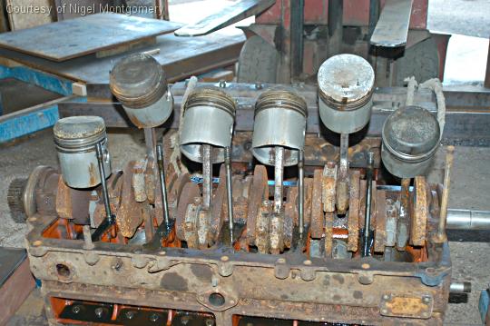 |
The pistons are manufactured of aluminum alloy. Each piston is fitted with three pressure rings and two scraper rings. The piston skirts are tin plated and are slightly oval. The piston crowns are specially shaped for flame control during combustion and as a consequence pistons from the left hand bank of the engine are not interchangeable with those from the right hand bank.
|
 |
|
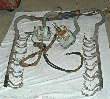 |
Spark plugs, Distributors and ignition wiring |
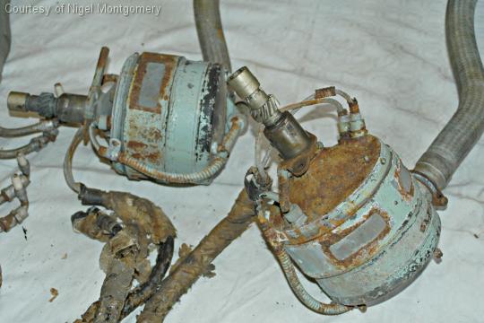 |
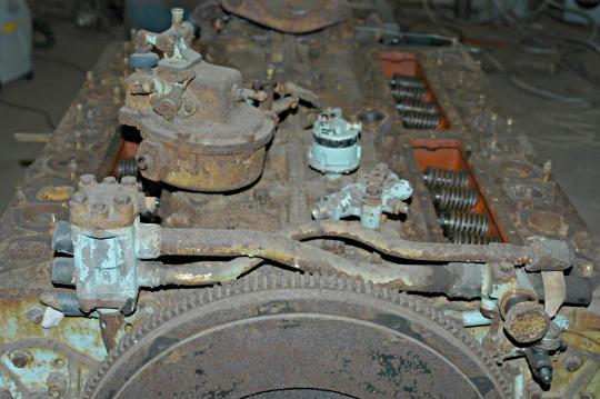
Close up of the two distributors. Each distributor is spigot mounted on the top of the crankcase, and is driven at half engine speed by a spiral gear on the corresponding camshaft. The distributor incorporates two six-cam circuit breakers and a centrifugal governor for automatic spark advance control. |
 |
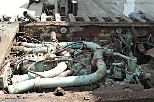
View of the transmission unit prior to removal. |
 |
|
 |
Attached to the top of the transmission unit is an air compressor. On each end of the transmission are attached the large steering brake drums. Each drum contains two brake shoes the adjustment holes for which can be clearly seen. On the left hand side can be seen the linkages for the gear selector rods incorporated on the gearbox input is a pulley wheel from which the turret traverse generator was driven. |