Late M3A1
Stuart III
Our subject
vehicles for this section are the Patton Museum's M3A1 (interior
photographs by Jon Hornbostle) and a privately owned vehicle
(photographed by Geoff Winnington-Ball of Maple Leaf Up)
 |
| © 1999 G.
Winnington-Ball |
 |
| © 1999 G.
Winnington-Ball |
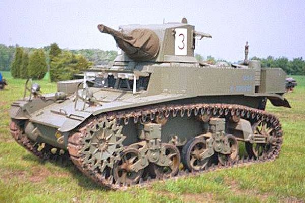
As you can
see from these two photos the exterior surfaces of the Late M3A1s
were devoid of any rivets being of welded construction. Lets now
have a look inside these two vehicles ....
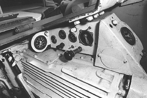
 |
| © 1999 J. Hornbostle |
|
| a |
Steering levers |
| b |
Transmission
oil pressure gauge |
| c |
Engine
Hour meter |
| d |
Stating
switch |
| e |
Booster
switch |
| f |
Hand
throttle |
| g |
Engine
oil pressure gauge |
| h |
Oil dilution switch |
| i |
Compass
mounting holes |
| j |
Brake
adjustment aperture plug |
| k |
Transmission |
| l |
Throttle
pedal |
| m |
Clutch
pedal |
|
 |
| © 1999 J. Hornbostle |
|
| a |
Steering
lever |
| b |
Brake
adjustment aperture plug |
| c |
Transmission |
| d |
Tachometer |
| e |
Engine
oil temperature gauge |
| f |
Ammeter |
| g |
Light
switch |
| h |
Volt
meter |
| i |
Headlight
dimmer switch |
| j |
Magneto
switch |
| k |
Priming
pump |
| l |
Dash
light switch |
| m |
Speedometer |
| n |
Dash
lights |
| o |
Oil
circulation test cock |
|
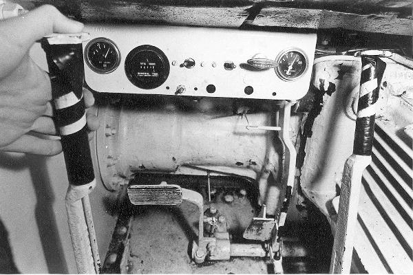
The driver's controls and
instruments are similar for all the M3 variants with the
exception of the M3A3 which due to it's sloping glacis has a
different layout.
The following images are
of the the turret interior. Neither of our two subject vehicles
is totally complete but in combination the images give pretty
complete coverage.
 |
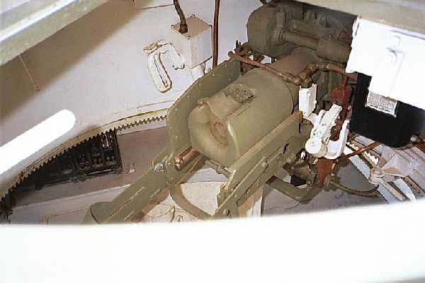
| © 1999 J. Hornbostle |
|
| a |
Elevating
wheel |
| b |
Linkage
to gunners periscopic sight |
| c |
Telescopic
sight |
| d |
Sight
head rest |
| e |
37mm
firing solenoid |
| f |
Cocking
handle |
| g |
Counter
weight |
| h |
Elevating
rack |
| i |
Gunners
seat |
|
The primary
sighting device in the M3A1 was the periscopic sight mounted in
the turret roof. As we can see from this photograph a direct
sight telescopic sight was also fitted but due to the shallow
turret basket this was difficult to use at higher elevations and
apparently was not particularly favoured. Missing from this
vehicle are the recoil guard and the gyro-stabiliser but these
items are shown in the photographs below of our other subject
vehicle.
 |
| © 1999
G.Winnington-Ball |
|
| a |
Radio Set |
| b |
Traverse
control handle |
| c |
Saftey
trigger |
| d |
0.30 MG
trigger |
| e |
37mm gun
trigger |
| f |
Stabilser
mounting bracket |
| g |
Stabiliser
grease nipples |
| h |
Commander's
perscope |
| i |
Gyro-stabiliser
control unit |
| j |
Stabiliser
recoil switch |
| k |
Cal .30
MG firing solenoid |
| l |
37mm
firing cable |
| m |
Traverse
lock |
| n |
Recoil
guard |
| 0 |
Cocking
handle |
|
This
photograph shows clearly the gunner's combined traverse control
and firing triggers. The various parts of the gyro-stabiliser can
also been seen fitted on this vehicle. In trials the
gyro-stabilser was shown to be quite effective but its use did
require a lot of training and practice. As a consequnece of this
the gyro-stabiliser was sometime removed where gunners had not
been given the required training experience. Missing is the
coaxial cal. 0.30 browning machine gun although parts of it's
mount are visible as well as the firing solenoid. In the
bottom corner we can see the radio set mounted on the left hand
sponson. This was the prefered side for the radio set as the
right hand sponson would usually be packed full of 0.30
ammunition boxes as both co-axial and hull machine guns are on
the right hand side of the vehicle.
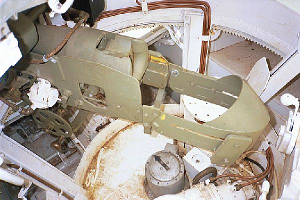 |
| © 1999 G.
Winnington-Ball |
|
| a |
elevating
wheel handle |
| b |
Hand
firing button |
| c |
37mm
firing solenoid |
| d |
Telescopic
sight mount |
| e |
Stabiliser
control unit |
| f |
Right
hand sponson |
| g |
Comander
seat |
| h |
Recoil
guard |
| i |
Manual
traverse handle |
| j |
Adjustable
counter-weight |
| k |
Stabilizer
hydraulic oil pump |
| l |
Traverse
electric motor |
| m |
Hydraulic
oil pot |
| n |
Slip ring
assembley |
| 0 |
Transmission
casing |
|
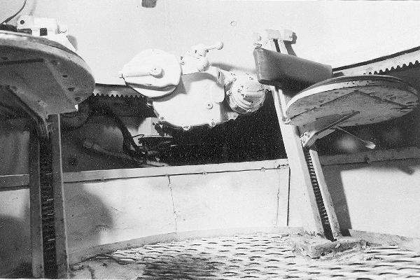
Moving back over to the left hand side of the gun we can see a
few more significant items of equipment have been revealed. The
recoil guard can be seen in full and we can see the slots through
which the adjustable counter-weight is mounted. In the centre of
the elevating wheel is a 'hand' firing button for the main
armament which although clearly visible in our earlier photo can
be seen to protrude from the elevating wheel in this one. Missing
from this vehicleis the telescopic sight. The white area in the
top left hand corner is, I assume, the mount for the gunners
periscopic sight. On the turret basket floor we can see the
equipment necessary for hydraulic traverse. The four lines going
around the right side of the turret are for the stabilizer and go
between a small pump on the far side of the motor and the hydraulic
cylinder on the right side of the gun. On the near side of the motor (out of shot) is
a pump for the tydraulic turret traverse. At the rear of
the turret can be seen the manual travers cranking handle which
leads us to our next photo.....
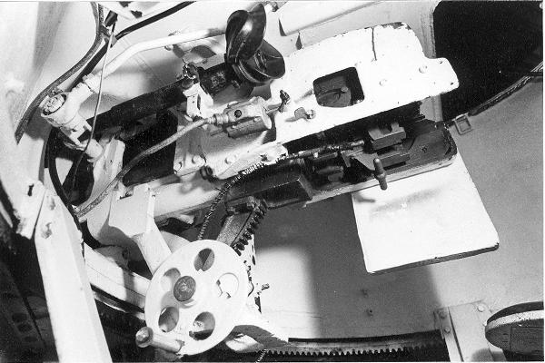
 |
| © 1999 J. Hornbostle |
Attached to
the rear of the turret is the traverse control gearing. On the
left is the manual crank, the lever on top is the clutch lever
and on the right we can see where the hydraulic power lines would
have connected. In this particular turret there is no evidence of
the hydraulic motor or pump assemblies shown in the previous
photograph. Where this equipment is remains a bit of a mystery as
we are not aware of any M3 hybrids or M3A1 tanks that only had
manual traverse. In the background we can see the
fire-extinguisher line passing through the rear bulkhead into the
engine compartment. We can clearly see the sprung seats of the
gunner and commander and also see the adjusting lever under the
gunner's seat. Note that the back rests for the seats are of a
different pattern to those of our other subject vehicle. The
shallowness of the turret basket meant that it was impossible for
the crew to stand when the turret hatches were closed and the rim
which partially surround the basket floor unfortunately meant
that there was no means of escape for the co-driver if the turret
was traversed. It is fair to say that the cramped nature of the
M3A1 turret was not liked and indeed M3A1 Stuarts of the Indian
7th Cavalry had their turret baskets removed.
 |
| © 1999 J. Hornbostle |
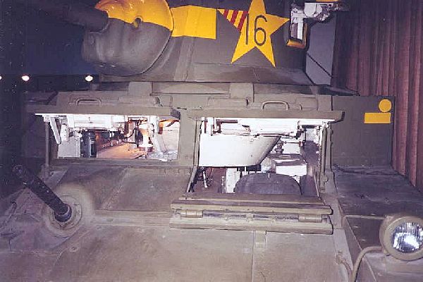
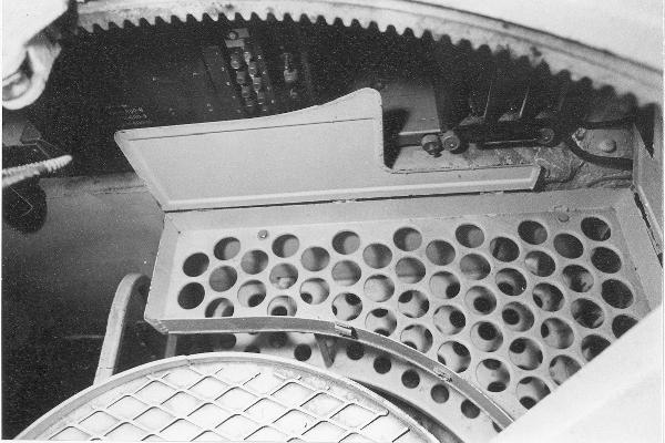
In this photo
we are pretty much sitting in the commander's/loader's seat
looking down at the turrt basket floor. Note that on the M3
hybrids and M3A1s the turret cupola was removed with the
commander gaining a periscope on the the right hand side of the
turret (the cupola on the M3 was on the gunners side). We can see
here a 37mm Ammunition bin which has two part hinged lid. One
part hinges towards the sponson and is clearly visible, the other
hinges up towards the bulkhead. In all 106 rounds of 37mm
ammunition were stored in the M3A1, more than half would appear
to be in this bin alone. Behind the hinged lid of the ammo box is
the SCR 508 radio set. In this vehicle the radio set is
positioned on the right hand sponson, which is somewhat
unexpected. It would be more usual for the radio set to be
positioned on the left and in command tanks the extra set would
be placed on the right at the expense of cal. 0.30 ammunition.
 |
| © 1999 J. Hornbostle |
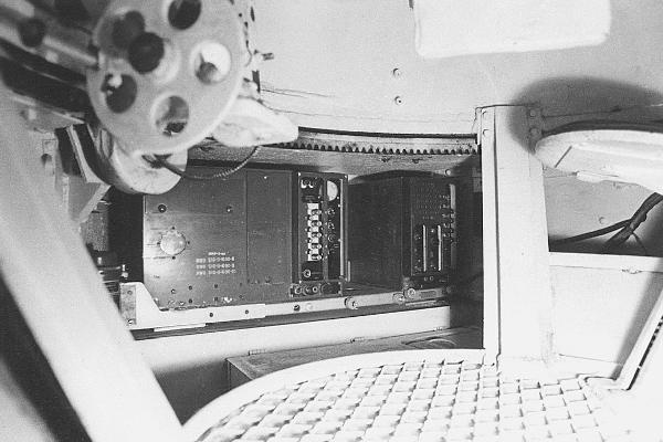
This photo is
of the same area as the previous one but from a lower position.
We can see that in this quadrant of the turret there is no wall
to the turret basket allowing easy access to the ammuntion rack
and, in this particular case, the radio sets, but only if the
turret is not rotated. It is through this area that the co-driver
would have to scramble to evacuated the vehicle. The ammunition
bin lids have now been dropped back into place to give a clear
view of the BC604 transmitter, RC298 interphone and BC603
receiver which make up the SCR 508 set. The positioning of the
radio set on the sponson must have been somewhat inconvenient for
the commander. The turret basket makes this area not paricularly
accesible, especially if the turret is traversed. In the
foreground we can see the elevating wheel of the main gun and
behind this we can see a turret support roller.
 |
| © 1999 J. Hornbostle |
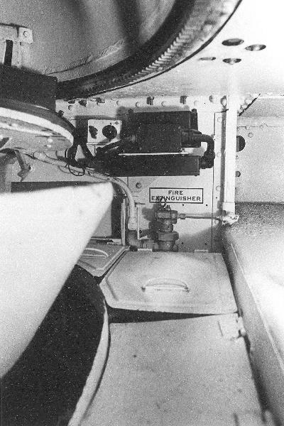
Mounted on the rear firewall is a fixed 10 lb
fire-extinguisher which supplies lines into the engine
cmpartment. Operation was by a lever on the top of the bottle or
from outside the tank by a hand lever on the left rear fender,
below the tail light. Unlike the M4 medium tanks, the driver was
not able to operate the main extinguisher system however there
was a smaller 5 lb portable extinguisher mounted by the drive
shaft casing behind the drivers position. As you can see this
particular part of the turret basket has high side to it - quite
why this was necessary I don't know as it must have hampered
access to the stowage bins and left hand sponson.
 |
| © 1999 J. Hornbostle |
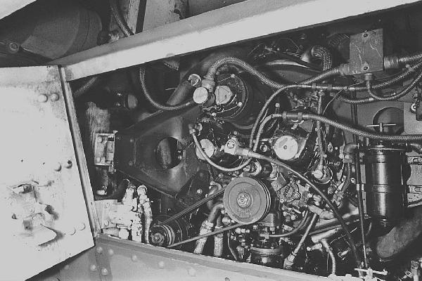
|
| a |
Generator |
| b |
Duplex
pressure and scavenger oil pump |
| c |
Magnetos |
| d |
Starter |
| e |
Starter
solenoid switch |
| f |
Fuel
filter |
| g |
Carburetor
body |
| h |
Fuel pump |
| i |
Governer |
| j |
Oil
temperature thermometer |
|
 |
| © 1999 J. Hornbostle |
|
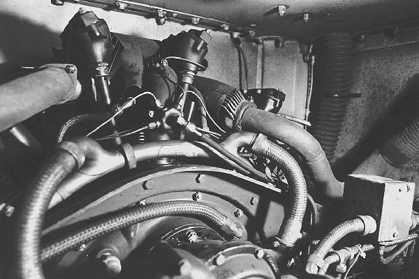
| a |
Starter |
| b |
Starter
solenoid switch |
| c |
Cylinder
heads |
| d |
Primer
distribution |
| e |
Hose to
air intake filter |
|
The above two
photographs show the engine comparment with Contimemtal W-670-9A
gasoiline engine fitted. Production of the M3A1 ran from May 1942
until February 1943. Of the 4621 tanks made during this period
all but 211 were fitted with the W-670 gasoline engine, the
remainder being equipped with Guiberson T1020 diesels.
Continental
W-670-9A Engine Specification
| Type |
Radial, Air
Cooled |
| Cylinders |
7 |
| Fuel |
80 Octane
Gasoline |
| Bore & Stroke |
5.125 in, 4.625
in |
| Displacement |
667 cubic ins |
| Compreesion |
6.1:1 |
| Max. governed
speed |
2,400 r.p.m. |
| Gross horse power |
262 at 2,400
r.p.m. |
| Max. gross torque |
590 lb-ft at
1,700 r.p.m. |
| Crankshaft
rotation |
counter clockwise |
| Length |
32 in |
| Width |
53.25 in |
| Height |
42.375 in |
| Ignition |
Magneto |
| Dry weight |
1070 lb |
| Weight installed |
1,214 lb |
© 1999 Jon Hornbostle, Geoff
Winnington-Ball & Chris Shillito