Interior Views - Lower Hull
M4A3 (105)
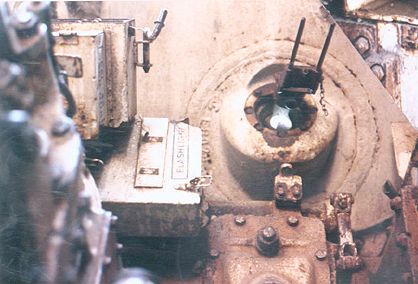
This photo was taken from the escape hatch mounted in the hull floor behind the co-drivers position. To the left is the bulk of the transmission casing from which can be seen emerging the rod of the speedometer adapter. On the bottom edge we can just glimpse the transmission filler cap (cylindrical object) and the top of the brake adjusting cover. Above the transmission we can see the .30 ammo read box with mounting straps fitted to hold a flashlight. Above and to the left of this is the periscope storage boxes shown in the pervious photo. The machine gun mount is clearly seen in this photograph (compare it with the M4A3E8 photo below). The fittings to the right and below the gun aperture are all part of the mount. The fitting directly below the aperture is an attachment point for a balancing spring. The strange fitting mounted on the side of the periscope storage boxes is, I believe, something to do with the MG travel lock.
M4A3 (105)
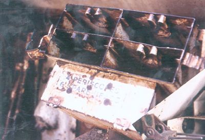
This photo shows the storage boxes for the 4 periscopes and 6 spare heads (in box below). These are mounted above the transmission between the driver and co-driver. Out of focus in the background can be seen the bulge of the brake adjusting hole cover. This photo has the one below overlapping at an angle so please ignore the right hand lower corner.
M4A3 (105)
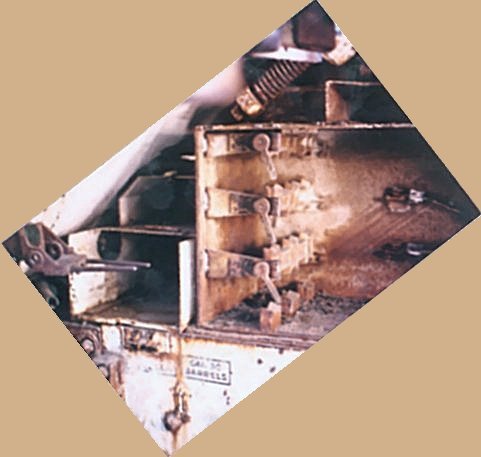
The photo above shows the area to the right of the bow MG. The slope of the front glacis is clearly visible as is the MG mount and the large hatch spring. Above and in front of the spring is a mounting for a periscope. The large stowage bin is for 9 105mm rounds. Unlike the later 75mm and 76mm gun tanks the 105mm howitzer tanks were not adapted to provide wet stowage of ammunition, however, armoured stowage bins for the 66 105mm rounds were introduced. Ammunition included the M1 42 pound HE shell and the M67 HEAT projectile, which was capable of penetrating 4" of armour at a normal impact. However it should be pointed out that the looping trajectory of shot given by the howitzer meant that the HEAT shell was only really a viable option at short ranges. The smaller adjacent bin held 3 boxes of 0.30 ammunition and immediately below this bin is an attachment point for a canteen. At the bottom of the photo (and clearly marked) can be seen the position where spare 0.30 machine gun barrels were stowed.
M4A3 (76)W
This photograph shows the bow machine gun in it's mounting. To the lower left are the periscope storage boxes.
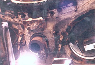
M4A3 (105)
Looking upward above the co-drivers and driver's position: To the right we can see the co-drivers hatch. Fitted into this hatch can be seen the mount for the rotating periscope. At the bottom of the photo (indicated by the brightly-lit areas) are the mounts for the fixed forward facing periscopes. The prominent circular fitting mounted between the driver's and co-driver's hatch is the where an air blower was fitted. At the top of the photograph we can see the turret ring.
M4A3 (76)W
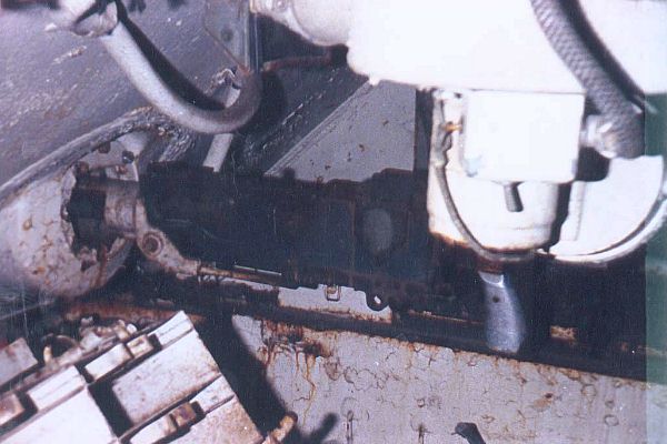
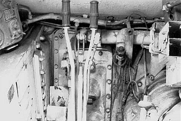
A good view of the drivers controls. In the centre we can see the two steering levers. The right hand lever has attached a button for operating the horn/siren. Behind the levers is the bulbous protrusion of the brake adjustment cover. The dark knob to the right of the steering levers is the hand throttle control, whilst the knob in the right-hand foreground is the gearshift lever. The mass to the right is the transmission and above it are (once again) the mounting boxes for the periscopes and spare heads. The rectangular plate at the bottom left of the left-hand steering lever is the clutch pedal. Mounted on the left-hand sponson can be seen the driver's control panel. On the left hand sidewall can be seen the position where the speed caution plate was once mounted.
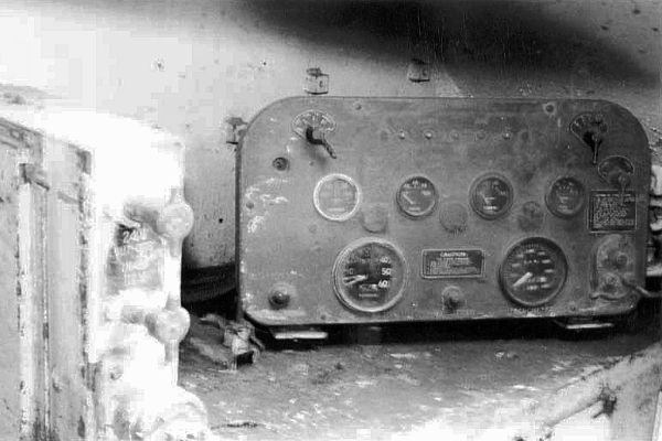
M4A3 (76)W
Driver's Control Panel: Starting at the bottom left the extreme left an indicator lamp indicating low oil pressure. The first large dial is the tachometer and the second large dial is the speedometer. Between these dials id a fuel cut off switch. On the right is the cranking motor and magneto switch. The second row of controls consists of four dials between which are mounted three panel light covers. The dials are as follows: ammeter, engine oil temperature, oil pressure and the fuel gauge. The top row has a panel light switch on the left ad the main light switch on the right. Mounted in between these two switches are five circuit breaker reset buttons. The reset buttons are for the following circuits/functions: fuel cut off, lights, accessories, siren and instruments

M4A3 (105)
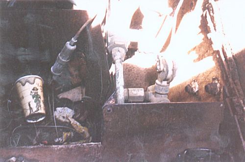
The above photo shows the rear bulkhead of the fighting compartment.
M4A3 (105)
The M4A3 had a fire extinguisher system, which consisted of both fixed and portable carbon dioxide extinguisher bottles. Clamped to the bulkhead were two ten pound fixed bottles, which fed six nozzles surrounding the engine. These bottles could either be operated from a control mounted near the drivers seat, or from outside the vehicle. In this photo of the base of the fighting compartment bulkhead we can see the attachment points for one of the fixed extinguisher bottles.
Images © 1999 Jon
Hornbostle
Text & html © 1999 Chris
Shillito